
 Audio
Audio
Lectrosonic UMC16B 16 Channel UHF Multi-Coupler
E-CODE: R8506-

Product Details
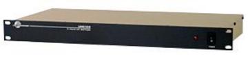
The UMC16B multi-coupler is used to distribute the signals from two antennas to eight diversity receivers to minimize the cabling and antennas needed in multi-channel wireless systems. The design combines broad band ceramic filtering with low noise, high intercept point RF distribution to provide outstanding performance and flexibility. Up to eight diversity receivers or up to 16 non-diversity receivers can be utilized across a 230 MHz passband.
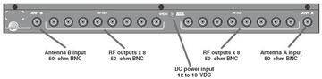
The UMC16B can be powered from an external supply, 12 to 18 VDC for mobile applications, or from 90 to 240 VAC for installations using the regulated power supply furnished with the unit. A locking connector on the rear panel secures the power connection.
The RF signals at the inputs first pass through a ceramic filter to block energy above and below the passband. The signal is then fed to a high current amplifier to apply the gain needed ahead of the splitter. The amplifier is a high current type with a very high IP3 (third order intercept) that minimizes intermodulation products.
The amplified signal is then distributed to the output jacks using a Wilkinson “strip line” RF splitter. The splitter design allows unused jacks to remain unterminated (no dummy loads needed) with no effects on the other outputs, which simplifies installation.
The unit is housed in a standard 19 inch rack mount assembly with rugged connectors.
Product Details
The UMC16B multi-coupler is used to distribute the signals from two antennas to eight diversity receivers to minimize the cabling and antennas needed in multi-channel wireless systems. The design combines broad band ceramic filtering with low noise, high intercept point RF distribution to provide outstanding performance and flexibility. Up to eight diversity receivers or up to 16 non-diversity receivers can be utilized across a 230 MHz passband.
The UMC16B can be powered from an external supply, 12 to 18 VDC for mobile applications, or from 90 to 240 VAC for installations using the regulated power supply furnished with the unit. A locking connector on the rear panel secures the power connection.
The RF signals at the inputs first pass through a ceramic filter to block energy above and below the passband. The signal is then fed to a high current amplifier to apply the gain needed ahead of the splitter. The amplifier is a high current type with a very high IP3 (third order intercept) that minimizes intermodulation products.
The amplified signal is then distributed to the output jacks using a Wilkinson “strip line” RF splitter. The splitter design allows unused jacks to remain unterminated (no dummy loads needed) with no effects on the other outputs, which simplifies installation.
The unit is housed in a standard 19 inch rack mount assembly with rugged connectors.