
 Video
Video
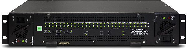
Evertz 5601AC02 Dual Auto Change Over System
E-CODE: Q2Q8D-

Product Details
The 5601ACO2 Automatic Changeovers are intended for use with two 5601MSC Master Clock/Sync Generators. The 5601ACO2 system uses latching relays to ensure maximum reliability and minimal disruption in the event of any failure. The complete system provides the highest level of security for television station video and time synchronization systems. The 5601ACO2 is a 2RU ACO for all outputs of the 5601MSC. Two power supplies are included as a standard feature, to alleviate any single point of failure concerns.
Manufacturer Specs
LTC/IRIG Inputs and Outputs
Standard SMPTE ST 12-1 frame rate set by 5601MSC or IRIG-B
Inputs 2 per 5601MSC
Outputs 2
Connectors
Inputs Female DB15
Outputs 3-pin male XLR type
Signal Level Set in 5601MSC
Coaxial Inputs and Outputs
Type Depends on signal connected from 5601MSC
HD-SDI, SD-SDI, Analog TG, AES, DARS, bi-level or tri-level sync, colour black, 10MHz, Word Clock
Number 16 groups each consisting of two inputs and one output
Connector BNC per IEC 61169-8 Annex A
ACO General Purpose Inputs and Output
Inputs
GPI1 Master select in Manual GPI control mode
Low Selects Master A
High Selects Master B
GPI2 Future use
Outputs
GPO1
Low Master A is selected
High Master B is selected
GPO2
Low Master A & Master B differ or PSU failure
High Master A and B have equivalent signals
Type
Inputs Opto-isolated input with internal pull-up to +5V
Outputs Normally closed relay to ground. 10kW internal pull-up to +5V when relay is in active position
Connector 4 pins plus 2 ground pins on 12-pin removable terminal block
Signal Level +5V nominal
MSC General Purpose Inputs and Output
Inputs 2 GPI inputs connected to both Master A and Master B
Outputs 2 GPI outputs connected from Master A through AUXI/O A
2 GPI outputs connected from Master B through AUXI/O B
Connector 6 pins on 12-pin removable terminal block
Signal Level As specified in 5601MSC manual
Changeover Conditions
Changeover is a voting system based on which source has the most good signals and that the good signals on the current master are also present on the backup master. The input signals are considered good according to the following criteria:
Video Level below 70 IRE
Sync H timing detect
10MHz 3dB level below 0.3V p-p
DARS Sync word error
LTC Level below 0.3V p-p
Incorrect sync word
Electrical
Power Auto ranging 100-240V AC, 50/60Hz, 40 Watts
Configuration Dual redundant supplies
Fuse Rating 250V, 1 amp, time delay
Safety ETL Listed, Complies with EU safety directives
EMI/RFI Complies with FCC Part 15 Class A, Complies with EU EMC Directive
Physical
Dimensions 19″ W x 3.5″ H x 11.5″ D
(483mm W x 90mm H x 292mm D)
Weight 16lbs (3.5kg)