
 Video
Video
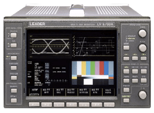
Leader LV 5700A HD/SD Waveform Vectorscope
E-CODE: Q268J-

Product Details
The LV 5700A is a waveform monitor for HD-SDI and
SD-SDI signals. Employs color TFT LCD screen.
The functions of waveform monitors, vectorscopes,
audio lissajous, and simple picture monitors are
achieved with a single unit.
Complete digital processing of SDI signals enables
highly accurate measurements. In addition, extensive
error detection functions and analysis functions are
provided which allow the LV 5700A to be used as SDI
signal monitor.
Manufacturer Specs
Video Format and Corresponding Standards
Video Signal Standards
Format Name Standard Supported
1080i/60
1080i/59.94
1080i/50
1080p/30
1080p/29.97
1080p/25
1080p/24
1080p/23.98
SMPTE 274M, 292M
1080PsF/30
1080PsF/29.97
1080PsF/25
1080PsF/24
1080PsF/23.98
SMPTE RP211, 292M
14
15
1035i/60
1035i/59.94 SMPTE 240M, 292M
16
17
18
19
20
21
22
23
720p/60
720p/59.94
720p/50
720p/30
720p/29.97
720p/25
720p/24
720p/23.98
SMPTE 296M, 292M
24
25
525i/59.94
625i/50 SMPTE 259M
Other Standards
Ancillary data standard: SMPTE 291M
Embedded audio standard: HD-SDI SMPTE 299M
SD-SDI SMPTE 272M
Format Setting
Video System: Select manual setting or automatic setting
Sampling Frequency: HD: Auto switching between 74.25 MHz and
74.25/1.001 MHz
SD: 13.5 MHz
Input/Output Connector
SDI Input
Input Connector: BNC connector 2 systems A and B, 75 Ω
External Reference Input
Input Signal: Tri-level sync signal or NTSC/PAL black burst
Input Connector: BNC connector passive loop-through 1 system
2 connectors
XGA Output
Output Signal: XGA signal
Output Connector: D-sub 15 pin female
SDI Output
Output Connector: BNC connector 2 connectors
One connector is a dedicated SD-SDI output
connector
Reclocks and outputs the selected SDI input signal,
75Ω
Analog Output
Output Signal: Y, PB, PR or GBR
Output Connector: BNC connector 1 system 3 connectors
AES/EBU Output
Output Signal: CH1/2, CH3/4, CH5/6, CH7/8
Separated from embedded audio and output
Select 2 groups (8 ch) from 4 groups (16 ch)
Output Connector: BNC connector 4 connectors
Remote Connector
Function: Recalling of presets
Control Signal: TTL level (LOW active)
Control Connector: D-sub 25 pin female 1 connector
Ethernet Connector
Function: Remote control from an external computer and
monitoring of errors, etc.
Input/Output Connector: 10BASE-T/100BASE-TX 1 connector(RJ-45)
Display Format
Display Format: XGA Effective area 1024 x 768 dots
1-screen display
Waveform display, vectorscope display, picture
display, audio display, and status display
2-screen display
Waveform display and vectorscope display
Waveform display and picture display
Waveform display and audio waveform display
4-screen display
Select audio waveform display, audio level meter
display, or status display in addition to waveform
display, vectorscope display, and picture display.
Waveform Display
Waveform Operation
EAV-SAV Period: Select show/hide
GBR Conversion: Select Y, CB, CR or GBR conversion display
Pseudo-Composite Display: Digitally converts component signals into composite
signals and displays the result (the color matrix
for HDTV signal is converted into SDTV)
Channel Assignment: Select GBR order or RGB order for GBR conversion
Display
Vertical Axis
Filter: Flat, low-pass
Horizontal Axis
Operation Mode
Overlay: Displays multiple waveforms overlaid
Parade: Displays waveforms side by side
Timing: Time difference between channels
Uses bowtie* signals
*Authorized by Tektronix, Inc.
Display Format
Line display: Overlay: 1H, 2H
Parade: 1H, 2H, 3H
Timing: 2H
Line Magnification: Select x1, X10, ACTIVE, or BLANK
Field Display: Overlay: 1V, 2V
Parade: 1V, 2V, 3V
Field Magnification: Select x1 or x20
Scale
Scale Display
Voltage Scale: 0 V to 0.7 V, -0.3 V to 0.7 V
% Scale: 0 % to 100 %, -50 % to 100 %
Vectorscope Display
Sensitivity: Select 75 % or 100 % Using a color bar
Gain: Select x1, x5, or IQ-MAG
EAV-SAV Period: Select show/hide
I, Q Axes: Select show/hide
Simple Picture Display
HD Display: Reduced display
SD Display: Magnified display
Embedded Audio Display
Lissajous Display
Display Channel: Select from 2 ch or 8 ch display
Display Method: Select X-Y or L-R
Sound Image Display
Display Channel: Select from 3-1 ch, 3-2 ch, and 3-2-2 ch displays
Peak Level Meter Display
Display Channel: Simultaneous 8 ch display
Display Method: Peak meter
Channel
Ch Mapping: Can be mapped arbitrary from 1 ch to 8 ch
Status Display
SDI Signal Status Display
Signal Detection: Detects the presence or absence of SDI signals
CRC Error: Transmission error of HD-SDI signals
EDH Error: Transmission error of SD-SDI signals
BCH Error: Transmission error of embedded audio signals in
the HD-SDI signal
Checksum Error: Transmission error of ancillary data
Gamut Error: Detects gamut errors
Composite Gamut Error: Monitors the level error when the component signal
is converted into composite signal
Audio Information Detection: Detects the presence or absence of audio on each
channel
Error Count: Up to 100,000 errors
V-ANC Monitor: NET-Q, CLOSED CAPTION
Data Dump Display
Display Format: Counts only the specified errors
Displayed separately by serial data sequence or
channel
Event Log
Number of Logs: Up to 1,000 events
Audio Status
Voice Control Packets: Analyzes and displays the voice control packets of
the SDI signal
EDH Display
EDH: Displays the status of the EDH packets
Line Selector
Operation Mode: Interlocked type between waveform display, vector
display, and picture display Preset
Presets
Number of Presets: 100 sets
Presets Items: All setup items
Recall Method: Through the front panel, remote connector, and
Ethernet Switch 8 points or 100 points are available
for recall through the remote connector
Cursor Measurement
Configuration: Horizontal cursor: 2 lines (REF, Δ)
Vertical cursor: 2 lines (REF, Δ)
Amplitude Measurement: Measured in [%] and [V]
Time Measurement: Displayed in [ms] and [ms]
Frequency Measurement: Displays the frequency in which the time between
cursors is considered a cycle.
Screen Capture
Capture: Captures the display screen
Waveform Comparison: Superimposes the input signal over an image from
memory.
Media: Internal memory (RAM) or compact flash card
Data Output: Save data in BMP format to a PC via a compact
flash memory card or Ethernet network.
Environmental Conditions
Operating Temperature: 0 to +40 ˚C
Operating Humidity: ≤ 85 % RH (without condensation)
Operating Environment: Indoor use
Operating Altitude: Up to 2,000 m
Pollution Degree: 2
Power Requirements
90 to 250 VAC, 50 Hz/60 Hz, 120 Wmax.
9 to 17 VDC(Option)
Dimensions and Weight
215 (W) x 133 (H) x 449 (D) mm 4.9 kg